Make 3D images may be difficult for beginners, where to start, but if you are a beginner already proficient in 2D it is not a problem, now living understanding of 3D images, the 3D image is a 2D image in extruded (made no height), its height will be visible when "WCS" was changed to be "UCS", for a position in the "WCS" 3Dnya image will not be visible, because the position of "WCS" the same as you see from the top. Imagine you see a matchbox when viewed from above, it is visible only rectangular shape alone, as if the match is just a rectangular course, now your position in the fox who had been looking over the current look of the door side, it would appear that matches turned out to have a height.
You should know extrude function will be in use when the object of the entity, such as a circle, ellipse and rectang, when you create a grid by using the "LINE", it has not become a single entity, you should perform the function of "PEDIT" or "REGION" sometimes while doing pedit difficult or often fail because there is a gap that is not visible to our eyes, it is often experienced by the drafter beginners.
The first step we prepare the layer or create a layer, on the commmand prompt type "layer"
 |
| Figure 1. The shape of the layer manager in the show. |
The intention of making the layer named "Table", is to separate between the table with the others, nothing else to ease when editing the picture, you need to consider "good image" is an image that is easily edited by others, do not ever make images in a single layer in the united dimension, hatch, and the image itself, it is this which will make it difficult when editing.
When finished click Apply and then OK, the image area will appear free of the dialog box, you now type "rectang" at the command prompt
When finished click Apply and then OK, the image area will appear free of the dialog box, you now type "rectang" at the command prompt
 |
| Figure 2. Functions rectang appeared to be enabled. |
Here you enter the value for the first coordinate value "0.0" then the coordinates of both the value of "1000.500", this means you are making a table top with a length 1000 and width of 500.
 |
| Figure 3. Figure rectang or rectangular when viewed from above. |
Note once again this box only in the form of a rectangle, and see the shape of the axis "X" and "Y" while the axis "Z" does not appear, this indicates the condition in the "WCS", where the axis "Z" is on top of her, now we change the position of being "UCS" by the way, point your cursor to the menu "View -> 3D Views -> Viewpoint Presets ..."
 |
| Figure 4. Selecting menu presets viewpoint. |
After the menu "presets viewpoint" in the next dialog select will appear
 |
| Figure 5. Dialog box to change the position of UCS. |
Fill the box "X Axis" with a value of 315 and the "XY Plane" with a value of 30, or you can do by clicking the box next to the right numbers 315 and 30 lower. Ma ka object display image will change.
 |
| Figure 6. Position UCS has begun to change the z-axis is already visible. |
Now you can see the axis "Z", so that when the object in extruded will appear amendment, at the command prompt type "extrude", the contents of height with a value of 20 while on his taper just press the enter button means we do not select a value, which in select default "<0>".
 |
| Figure 7, the sequence of steps extrude. |
This is the result extrude the box table
This table still looks rough every corner still spiky, do not think about it but now is the time to be ahead of the finishing, including the color of the line where there are red in color wood, which will be discussed here tricks and how to make 3D, another later in the session will discuss matter other.
Now you create a new layer named "Table Leg" and set to "current set", at the command prompt type "Xline" and made to "h" and "v", and select the bottom corner of the table, then in the offset of the second The line towards the inside with a range of 100, these help lines to create a loop that will be made in the foot of the table, continue to make a circle with a center point of intersection of the auxiliary lines, note in Figure 10.
 |
| Figure 8. Results of the extruded rectangular box. |
This table still looks rough every corner still spiky, do not think about it but now is the time to be ahead of the finishing, including the color of the line where there are red in color wood, which will be discussed here tricks and how to make 3D, another later in the session will discuss matter other.
Now you create a new layer named "Table Leg" and set to "current set", at the command prompt type "Xline" and made to "h" and "v", and select the bottom corner of the table, then in the offset of the second The line towards the inside with a range of 100, these help lines to create a loop that will be made in the foot of the table, continue to make a circle with a center point of intersection of the auxiliary lines, note in Figure 10.
 |
| Figure 9. A series of steps using Xline and offset. |
 |
| Figure 10. Two help lines to create a circle. |
Layer "table" in order to facilitate the switch off when creating a "table leg", so we just focus on the foot of the table, this table will we set at a height of about 45 cm or 450 mm from the floor up to the top surface of the table, so the table legs must The decrease in the thickness of the table is 20, so the table legs will we extrude 450-20 = 430 mm, downwardly "-430" (use the minus sign means to extrude downward.
 |
| Figure 11. Leg table was formed. |
When you create a table leg visible only in the form of two circles and two vertical lines, immediately set "isolines" to a value of 12 and then in the "regen".
It feels a table leg straight if only just a little less sense of touch of art, we would make a little better there good shape in view, type "circle" select circle at the bottom and select the quadrant with a radius of 10, then in extruded as high as 150, continued in "array "polar choose the number 12.
 |
| Figure 12. Sequence and step circle, extrude and arrays. |
 |
| Figure 13. The circle is in extruded later in the array. |
The next step is to do "subtract" and the results are seen in Figure 14
 |
| Figure 14. Leg table after subtract. |
Help lines immediately clear because it is no longer needed, layer "table" so that in turn it back on, it will be done in the "mirror", select the midpoint at the width of the table to the left and the right.
 |
| Figure 15. Sequence step foot table mirror. |
 |
| Figure 16. The results mirror at the foot of the table. |
Next do mirror against a table leg by selecting the midpoint of the length of the table
 |
| Figure 17. Leg table is complete. |
Final touch is to "fillet" against the table top to make it look nicer, to the corner of the fillet with a radius of 25 and a length and width of the side with a score of 5.
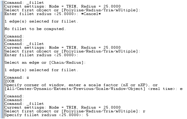 |
| Figure 18. Sequence of steps to fillet on the table. |
 |
| Figure 19. The final shape of the table. |
Table we will change the color to natural wood color, point your cursor to the menu "View -> Render -> Materials ..."
 |
| Figure 20. Directions towards menu material. |
After selecting the menu dialog appears this material.
 |
| Figure 21. Dilaog for the material. |
Then you select it again or press the "MaterialsLibrary ..."
 |
| Figure 22. Dialog Boxes library material. |
In the box "Current Library" or rightmost select "Wood.Med.Ash" or up to you, click on the button "Import -> OK". After 22 images at the click OK and then disappeared left behind the dialog box image 21.
In the "Materials" clicked "Wood.Med.Ash" continues at the click of a button "Attach" and select all objects, then on OK, again point your cursor to the menu "View -> Render -> ... rendering renders (at diaalog box ) ".
This is the final result of the table that you created
 |
| Figure 23. The final result of your creations table. |
Tag :
Tutorial AutoCad

0 Komentar untuk "Make 3D For Beginners"